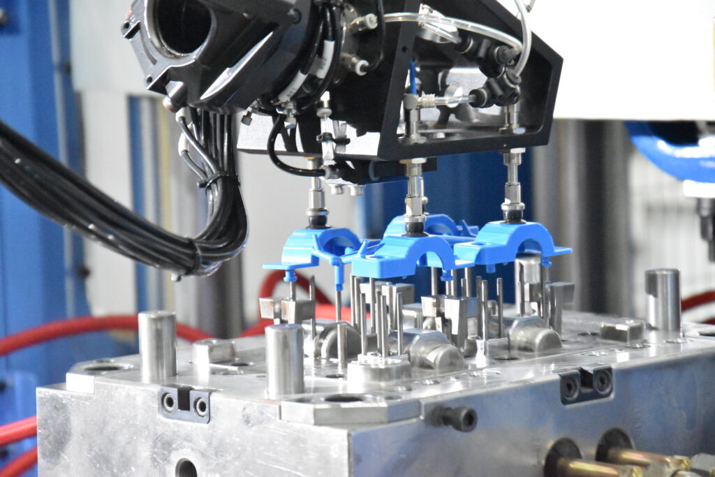
A professional injection molding supplier can shorten product development by finding manufacturability issues before tooling starts, selecting workable resins, planning gates and cooling, validating dimensions, and controlling process conditions during trials. A 0.5 mm wall change, a 1° draft adjustment, or a gate moved 10–20 mm can affect filling, warpage, sink marks, and tool modification cost. For projects targeting 100,000–1,000,000 parts per year, reducing a 30-second cycle to 25 seconds cuts molding time per shot by 16.7%. Supplier support is most useful before steel is cut, because CAD changes usually cost far less than mold rework.
Product development normally starts with a 3D model, drawing, resin requirement, expected annual volume, cosmetic standard, and assembly conditions. Before mold design, the supplier should review wall thickness, ribs, bosses, undercuts, draft, tolerances, parting lines, gate position, ejection, and areas that may trap air.
A part that looks simple on screen can behave differently when molten polymer enters a cavity at high speed. Typical injection pressures can exceed 70–140 MPa depending on resin, geometry, machine setup, and flow length, so thin sections and abrupt thickness changes deserve attention before tooling begins.
A dimensional issue found in CAD may require a drawing revision. The same issue found after T0 sampling can require welding, machining, polishing, another trial, and another dimensional inspection.
That difference makes early DFM work practical rather than administrative. For many molded products, nominal wall thickness may fall around 1–4 mm, although suitable thickness depends on resin, flow length, stiffness requirements, ribs, and product geometry.
Draft should be reviewed at the same time because molded plastic contracts around cores during cooling. Around 0.5–1° per side may work on some polished surfaces, while textured surfaces often need more; deeper textures can require several additional degrees depending on the texture specification.
Wall design then connects directly to material behavior. Mold shrinkage is not one fixed number: many amorphous plastics may shrink below 1%, while semi-crystalline polymers can exceed 1–2%, and reinforced grades can behave differently along and across fiber orientation.
Material selection therefore needs both performance data and processing data. A supplier should review:
-
service temperature and heat exposure;
-
tensile, flexural, and impact requirements;
-
chemical and UV exposure;
-
moisture absorption;
-
flammability classification where required;
-
shrinkage and dimensional stability;
-
surface appearance and color;
-
expected annual volume and resin price;
-
recycled-content or regulatory requirements.
For example, a 30% glass-fiber reinforced grade may improve stiffness compared with an unfilled version, but fibers also influence surface appearance, shrinkage direction, tool wear, and warpage. A housing with four screw bosses can pass strength requirements and still distort enough to create a 0.3–0.5 mm assembly mismatch.
Once the resin family is chosen, gate design becomes easier to evaluate because viscosity and filling behavior are better defined. A gate placed near a thick section may support packing, while a poorly located gate can create a visible weld line, excessive shear, hesitation, or uneven shrinkage.
Simulation can help before metal is machined. Filling studies can estimate pressure, flow-front movement, weld-line location, air traps, temperature, packing behavior, clamp-force demand, cooling differences, and warpage risk.
| Engineering item | Typical question before tooling | Production effect |
|---|---|---|
| Wall thickness | Is the section uniform enough for the selected resin? | Fill balance, sink, cooling time |
| Gate | Can melt reach thin or distant areas without excessive pressure? | Weld lines, packing, appearance |
| Cooling | Are hot spots concentrated near ribs or bosses? | Cycle time, warpage |
| Ejection | Is enough draft available on deep walls? | Scuffing, deformation |
| Tolerance | Is the drawing tighter than the process needs? | Scrap, inspection cost |
Simulation results still need physical trials because machine condition, steel temperature, resin lot, venting, cooling-water flow, and actual tool finish affect the molded part. T0 and T1 samples provide the first opportunity to compare predicted behavior with measured parts.
A structured trial should record melt temperature, mold temperature, fill time, injection pressure, transfer position, holding pressure, holding time, cooling time, screw recovery, and overall cycle. If a supplier changes several settings without recording them, repeating the same condition 6 months later becomes difficult.
Dimensional inspection should follow enough cooling and conditioning time for the material being used. Some polymers continue to change after ejection due to thermal contraction or moisture uptake, so measuring only the first five hot parts can give a poor picture of production dimensions.
For a part with 25 drawing dimensions, not every dimension needs equal inspection frequency. Assembly datums, sealing surfaces, bearing fits, connector positions, snap geometry, and hole spacing usually deserve more attention than non-functional cosmetic dimensions.
Production qualification is stronger when parts from more than one cavity and more than one molding cycle are measured, rather than approving one attractive sample from the first shot.
A four-cavity mold, for example, can produce four slightly different dimensional populations because cavity pressure, cooling, venting, or gate condition may vary. Measuring 5 parts from each cavity gives 20 samples and provides more information than measuring 20 parts from cavity 1 alone.
Tool design should also match the expected production quantity. A program requiring 5,000 parts for market validation does not automatically need the same tooling approach as one expected to produce 2 million parts over several years.
Lower-volume projects may use simpler tooling, manual inserts, fewer cavities, or less automation. Higher-volume programs may justify hardened steel, replaceable wear inserts, hot runners, automatic unscrewing, robotic handling, or additional cavities because machine time and labor are spread over a larger number of parts.
Cycle time becomes important as volume rises. At 500,000 parts per year, reducing a single-cavity process from 30 seconds to 25 seconds removes about 694 molding hours before allowance for downtime, changeovers, scrap, and maintenance.
That calculation leads naturally to cooling design because cooling often occupies a large share of the molding cycle. Water-channel position, diameter, flow rate, mold temperature, steel conductivity, and local part thickness can all affect how soon a part can be ejected without deformation.
Thick bosses are a common example. A boss attached to a 2.0 mm wall but built with excessive base thickness can cool more slowly than the surrounding surface, increasing sink risk and extending the time needed before ejection.
Ribs need similar care. A rib that is too thick compared with the adjoining wall can leave a visible depression on the opposite cosmetic surface, so designers commonly keep rib thickness below the full nominal wall thickness and adjust height, draft, and spacing around the structural requirement.
Tool changes should also be planned before steel cutting. If a connector opening, snap feature, or branding area is likely to change during validation, using a replaceable insert can make a later revision smaller than modifying the complete cavity block.
A supplier supporting new development should explain what can be changed by steel removal and what requires adding material. Removing 0.20 mm from an insert can be straightforward; adding 0.20 mm back may require welding, a replacement insert, surface restoration, or additional qualification depending on the location.
Tolerance discussions deserve the same level of attention. Plastic dimensions are affected by part geometry, resin shrinkage, fiber orientation, mold temperature, pressure history, moisture, and measurement method, so applying ±0.05 mm across an entire drawing can increase tooling and inspection work without improving product function.
A better approach is to separate functional dimensions from general dimensions. If only 6 dimensions in a 40-dimension drawing affect assembly, sealing, or product performance, those 6 can receive tighter controls while the others use realistic molding tolerances.
That approach also makes process capability studies more useful. When production volume justifies statistical evaluation, repeated measurements can show whether a dimension stays comfortably inside specification rather than merely passing one inspection lot.
The Plastic injection molding solutions provider should also consider post-molding work before mold design is released. Inserts, ultrasonic welding, heat staking, printing, painting, laser marking, CNC operations, gasket installation, and final assembly can all place additional requirements on molded geometry.
An ultrasonic-welded housing, for instance, needs a joint geometry suitable for energy transfer and part alignment. A heat-set threaded insert requires sufficient boss diameter and wall support so insertion does not split the boss or deform a nearby cosmetic wall.
Surface requirements affect tooling choices as well. A Class-A cosmetic face may restrict gate, ejector, weld-line, and parting-line positions, while an internal bracket may allow those features in locations that reduce tool complexity and shorten the molding cycle.
Quality planning then connects engineering development with repeat production. Before production release, the supplier should have an approved resin specification, drawing revision, mold identification, process window, inspection plan, packaging method, and reference samples where appearance standards cannot be expressed by dimensions alone.
Traceability becomes more important as annual volume grows. A project producing 1 million parts in 2026 may need lot records linking molded parts to resin batches, production dates, machines, molds, cavities, and inspection records, especially where customer requirements call for documented manufacturing history.
Maintenance planning belongs in the same discussion. Slides, lifters, ejector pins, vents, gates, hot-runner components, seals, and textured surfaces wear at different rates, and abrasive glass-filled materials can increase maintenance demand compared with many unfilled grades.
A supplier should therefore estimate tool life together with expected volume rather than quoting tooling as a one-time purchase. If a program needs 1.5 million parts, maintenance access, spare components, replaceable inserts, and cavity refurbishment can matter more than saving a small percentage on initial mold cost.
Communication affects how quickly engineering changes move through development. A useful supplier response should state the drawing revision, affected feature, proposed mold change, dimensional impact, expected sample quantity, and whether the modification changes lead time or tooling cost.
During a normal development cycle, a customer may review 2–4 sample rounds before final approval, although simple products may need fewer and demanding assemblies may need more. Clear records prevent teams from comparing a T2 sample against an outdated T0 drawing.
For new products, supplier performance can therefore be judged through measurable work: DFM findings before tooling, controlled mold trials, cavity-based dimensional data, recorded processing conditions, documented tool changes, repeatable inspection methods, and stable production output across the required annual volume.